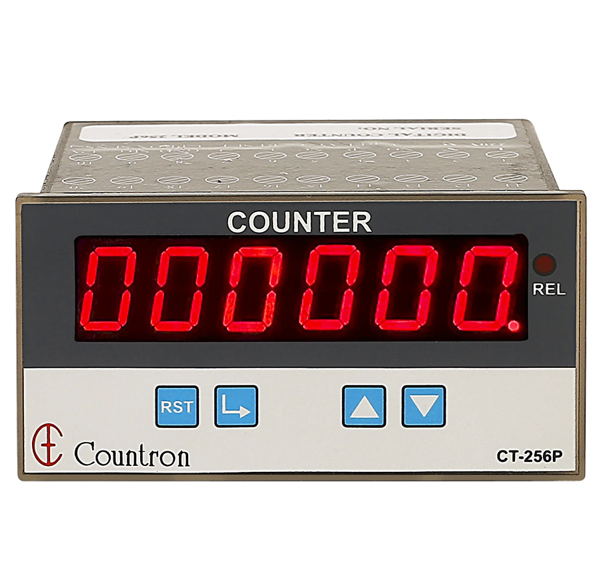

Programmable Digital Counter – Model 256 p 1 – Countronics

Counter And Tachometer Input Wiring: NPN vs PNP Sensors, Contact Inputs And Noise Problems

In short: An NPN sensor switches the signal to 0 V (sinking); a PNP sensor switches it to +V (sourcing). The counter’s input must match. Use a debounce/low-speed setting for mechanical contacts, and run sensor cables away from motor wiring with the shield earthed at one end to stop false counts.

NPN vs PNP

NPN (sinking)PNP (sourcing)
Output when activePulls signal to 0 VPushes signal to +V
Common inAsian and older equipmentEuropean equipment, many PLCs
Wire colours (typical)Brown +V, Blue 0 V, Black signalBrown +V, Blue 0 V, Black signal

The colours are the same — the label on the sensor tells you which type it is. Connecting the wrong type usually means no counts at all.

2-Wire vs 3-Wire Sensors

3-wire sensors (supply, 0 V, signal) are easiest to interface. 2-wire sensors draw a small leakage current even when off, which some inputs read as ON — check compatibility.

Mechanical Contacts

Limit switches, reed switches and relay contacts bounce for a few milliseconds when they close, producing several pulses. Use the counter’s low-speed or debounce input, or an electronic sensor instead.

Stopping False Counts

  • Separate sensor cables from motor, VFD and heater cables
  • Use shielded cable, shield earthed at the instrument end only
  • Keep cable runs as short as practical
  • Add RC suppressors across contactor coils nearby
  • Check sensor supply voltage is stable

Countronics counters and tachometers provide sensor supply for proximity sensors. Related: tachometer types.

Mistakes to Avoid

  1. PNP sensor on an NPN input.
  2. High-speed input used with a bouncing contact.
  3. Sensor cable tied to motor cables.
  4. Shield earthed at both ends.

Quick Checklist

  • Sensor type matches input
  • Debounce for contacts
  • Cable separated and shielded
  • Supply voltage checked
  • Test count against a known number

Frequently Asked Questions

What is the difference between NPN and PNP sensors?

An NPN sensor switches the output to 0 V when active; a PNP sensor switches it to the positive supply.

Why is my counter not counting with a new sensor?

The sensor type (NPN or PNP) may not match the counter input, or the supply is not connected.

Why does a limit switch give extra counts?

Mechanical contacts bounce; use a debounce or low-speed input.

How do I stop false counts from motors?

Route sensor cables away from power cables, use shielded cable earthed at one end, and suppress nearby contactor coils.

Can 2-wire proximity sensors be used with counters?

Sometimes, but their leakage current can be read as ON; check the counter input specification.

Wiring A Sensor To A Counter?

Countronics counters and tachometers support common proximity and photo sensors. Tell us your sensor model and we will advise.


In short: Measure conductivity of feed and permeate. Salt rejection % = (1 − permeate ÷ feed) × 100. A healthy RO often rejects around 95–99 %. A falling rejection or rising permeate
RO Plant Monitoring: Feed And Permeate Conductivity, Salt Rejection Calculation And Alarm Settings
In short: After a power cut, a timer either resets (starts again from zero), or resumes from where it stopped. Resume is essential for long processes such as curing and soaking; reset is
What Happens To A Timer When Power Fails? Reset, Resume And Battery Backup Explained
In short: Total measurement error = instrument error + sensor error + installation error. A logger rated ±1 °C with a standard thermocouple can easily be off by several degrees in total. Resolution
Data Logger Accuracy And Calibration: What ±1 °C Really Means And How To Verify Each Channel