

Countronics
Categories: Humidity Controller
📘 Part of the Temperature Measurement Knowledge Hub — guides on thermocouples, PT100, controllers and data logging.
| Symptom | Likely cause | Check / fix |
|---|---|---|
| Reading falls as temperature rises | Reversed polarity at a joint | Check + and − at sensor, junction box and instrument |
| Error grows with temperature | Wrong type selected (e.g. K wire on J setting) | Match the instrument setting to the sensor |
| Error changes with junction-box or panel temperature | Copper or wrong-type extension cable | Replace with matching extension/compensating cable |
| Reads room temperature only | Short circuit in cable, or junction at wrong place | Check cable for damage; a short creates a new junction |
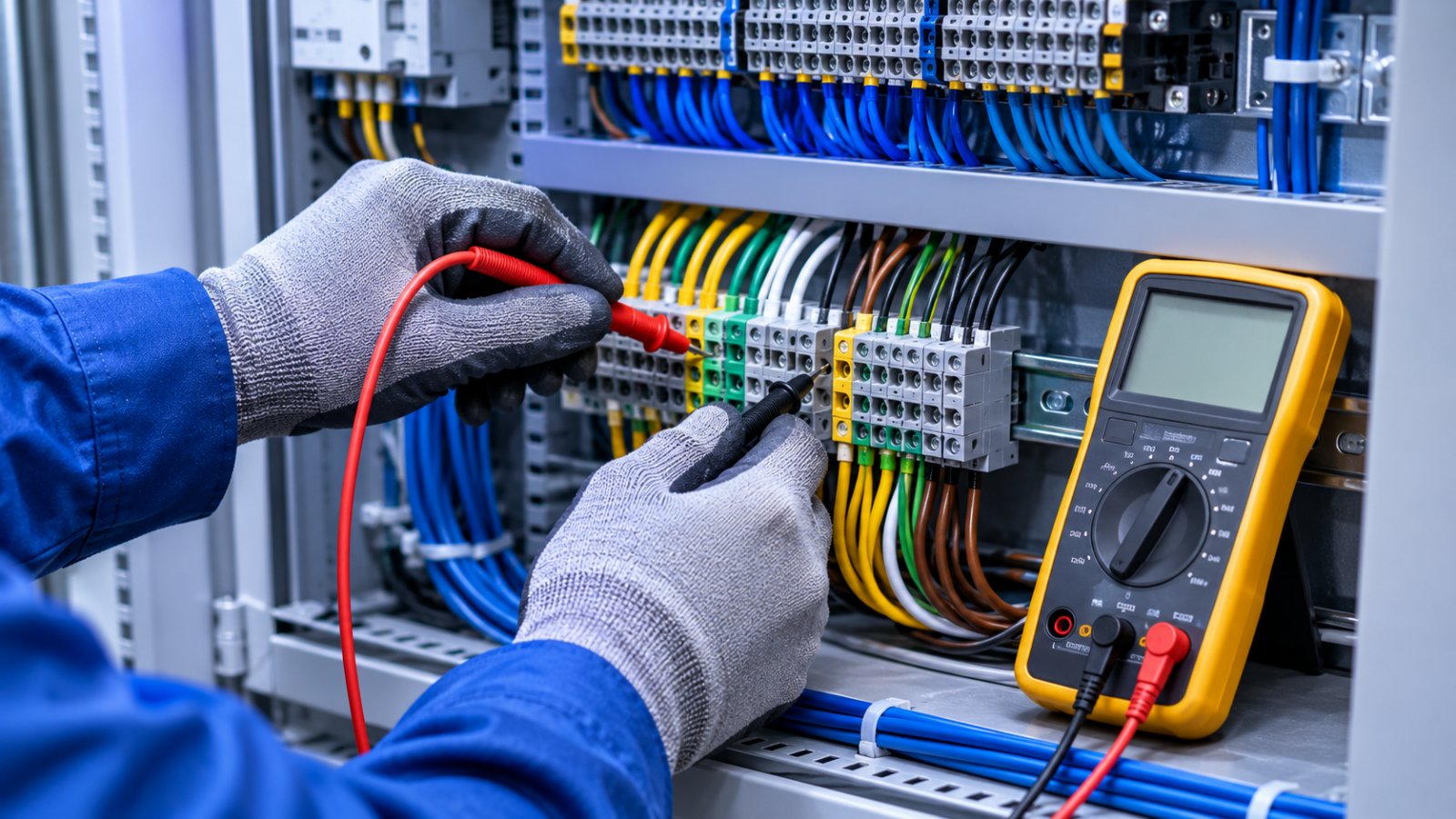
| Display shows open, maximum or error | Broken sensor or loose wire | Check continuity — a K thermocouple is typically a few ohms |
| Jumping, noisy reading | Electrical noise, ground loop, grounded junction | Separate from power cables, use screened twisted pair, try ungrounded probe |
| Slowly reading low over months | Drift (e.g. K above 1000 °C) or green-rot | Compare with a reference; replace sensor |
Thermocouple signals are only tens of microvolts per degree, so induced noise is significant. Run thermocouple cable separately from motor and heater power cables, use twisted screened cable with the screen earthed at one end, and prefer ungrounded junctions with multi-channel instruments. In electrically heated furnaces, leakage current through hot insulation can reach a grounded junction and disturb readings.
Replace thermocouples that have been used for long periods near their upper limit, show visible oxidation or embrittlement, or fail a comparison check. In critical heat treatment, follow a scheduled replacement or calibration plan. For more background see how a thermocouple works and the Type K guide.
Usually the wrong type is selected, polarity is reversed somewhere, or copper/wrong-type extension cable was used. Check these before replacing the sensor.
Check continuity and resistance, then compare it with a reference thermometer. Test the instrument separately with a millivolt calibrator.
Typically a few ohms for a probe, more for long or fine-wire runs; an open circuit reads very high or infinite.
Electrical noise or ground loops — separate cables from power wiring, use screened twisted cable, or use an ungrounded junction.
It depends on temperature and atmosphere; sensors used near their upper limit drift and should be checked or replaced on a schedule.
Countronics makes temperature controllers, indicators and calibrators for checking thermocouple loops. WhatsApp us your symptom and we will help.
By Countronics
By Countronics

By Countronics
© 2026 - countronics.com
WhatsApp us